-40%
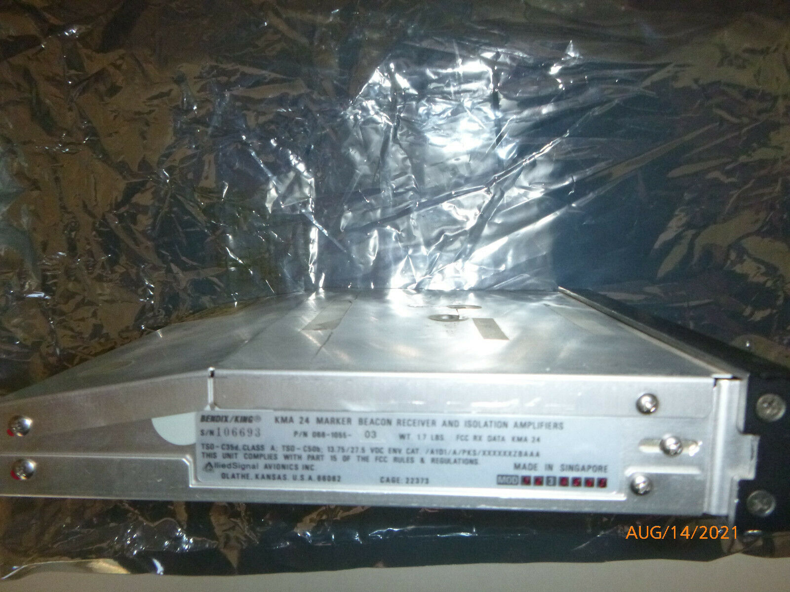
Bendix King KMA-24 Marker Beacon Rec & Isolation Amplifier P/N 066-1055-03
$ 124.59
- Description
- Size Guide
Description
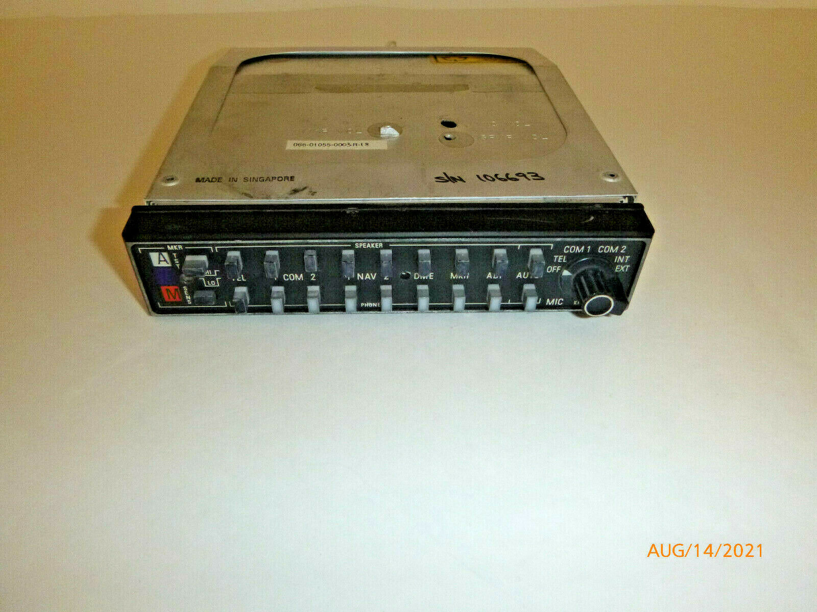
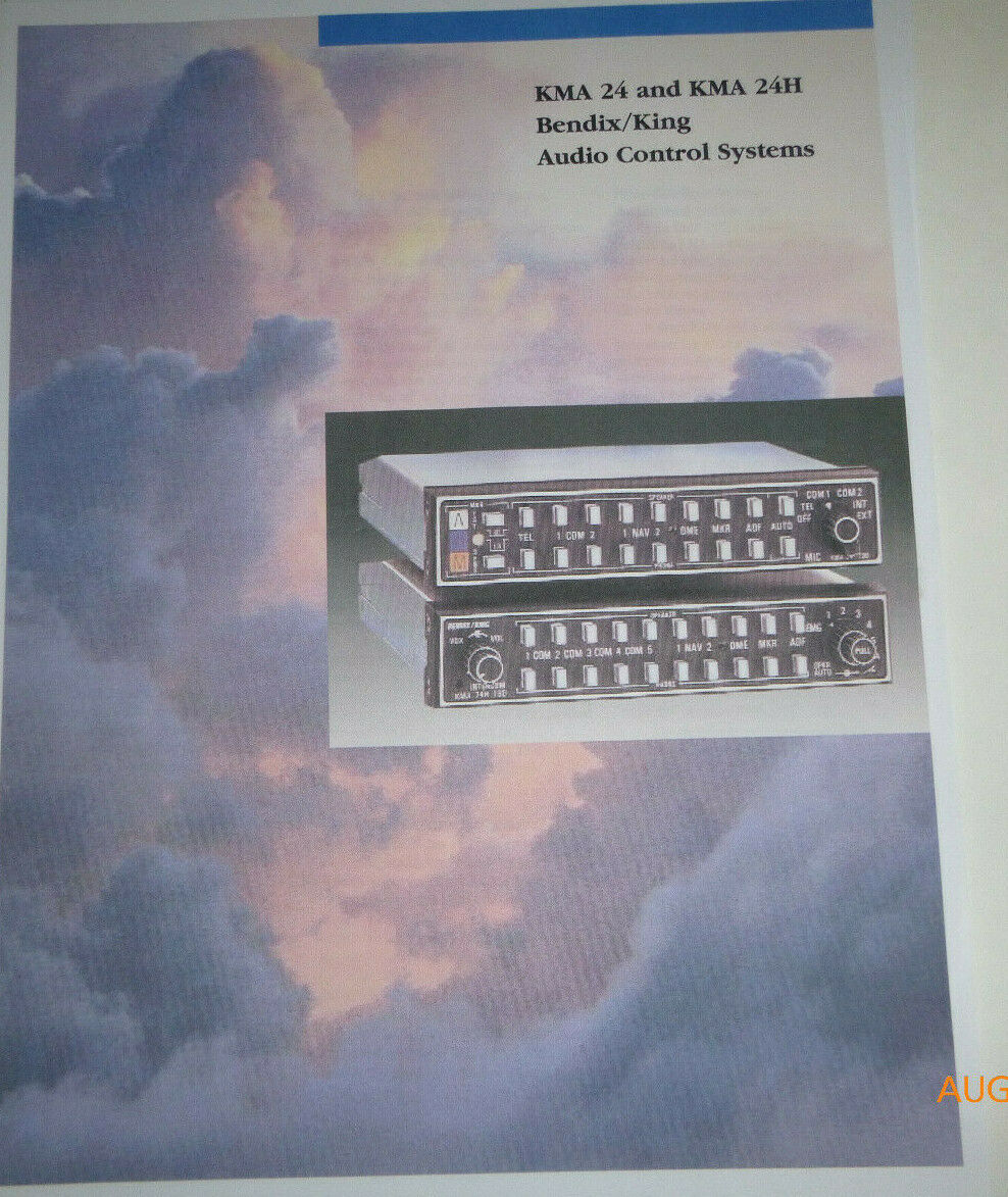
The audio panel is the KMA 24, probably one of the most common audio panels found in GA planes.In an overall view, the KMA 24 audio panel has two rows of buttons, flanked on the left by marker beacon lights and on the right by a rotary knob whose principle function allows the user to select COM 1 or COM 2. The top row of buttons directs the selected audio output to the speaker in the aircraft. The bottom row of buttons directs the selected audio output to your headset.
1.
Marker beacon lights are used in many ILS instrument approaches. If the ILS approach has marker beacons (not all of them do), the most common ones are the outer marker (the blue light marked “O”) and the middle marker (the amber light marked “M”). The inner/airway marker (the white light marked “A”) is generally only installed at major airports. Marker beacons emit a 75-Mhz signal. When the aircraft passes over an outer marker, the blue marker beacon light is seen. A middle marker beacon illuminates the amber marker beacon light. In addition, an audible tone may be heard. If you want the audible signal to come through the speaker, press MKR (#9) on the top row of buttons. If you want it to come through your headset, press MKR on the bottom row of buttons.
a.
The 75 Mhz signal transmitted by the marker beacons is a carrier frequency. This carrier frequency is modulated into a 400 hz, 1300 hz or 3000 hz signal for the OM, the MM, and the IM respectively.
2.
TST - test the marker beacon lights. Pressing this button causes all the marker beacon lamps to illuminate. SENS - the button just to the right of the amber marker beacon lamp selects the sensitivity of the marker beacons. HI allows the marker beacon signal to be detected approximately one mile before passing over the beacon. At this point, if you had HI sensitivity selected, you would want to switch to LO sensitivity. A word of caution concerning the TST button. Bendix King notes that the TST button should not be pushed when the autopilot is coupled on an ILS approach. Some autopilots, including Bendix King models, use the marker beacons to change the sensitivity of the autopilot. Next to the “O” marker beacon lamp is a photoelectric cell which controls the brightness of the marker beacon lamps.
3.
TEL – controls audio for a radio telephone. Alternately some KMA 24 audio panels replace the TEL function with HF, for operation with a high frequency transceiver. Note that this function, either TEL or HF, must also be selected on the rotary knob on the right side of the audio panel.
4.
1 COM – controls audio received from COM 1 communications radio. Again, the top row button directs output to the aircraft speaker, and the bottom row button directs it to your headset.
5.
COM 2 – controls audio received from COM 2 communications radio.
6.
1 NAV – controls the audio received from the NAV 1 radio. This includes any weather information, such as HIWAS as well as the Morse code IDENT. Many nav radios have a switch on the radio for IDENT. This must be selected in addition to selecting either speaker or headset for the audio.
7.
NAV 2 – ditto for the NAV 2 radio.
8.
DME – allows you to hear the Morse code identifier for any DME that is co-located with VOR or localizer stations. Most DME receivers have the ability to enter a frequency separately from the nav radios. However the most common method of operation is to remote the DME receiver to either nav 1 or nav 2.
9.
MKR – allows you to hear the marker beacon audio signals.
10.
ADF – allows you to hear the Morse code identifier of an NDB station. During an NDB approach, most instructors teach their students to keep the Morse code identifier for the NDB on during the entire approach to verify integrity of the signal. Unlike VOR receivers, ADF receivers do not display an OFF flag, so the Morse code is the only way to ensure the data being received by the ADF receiver is valid.
11.
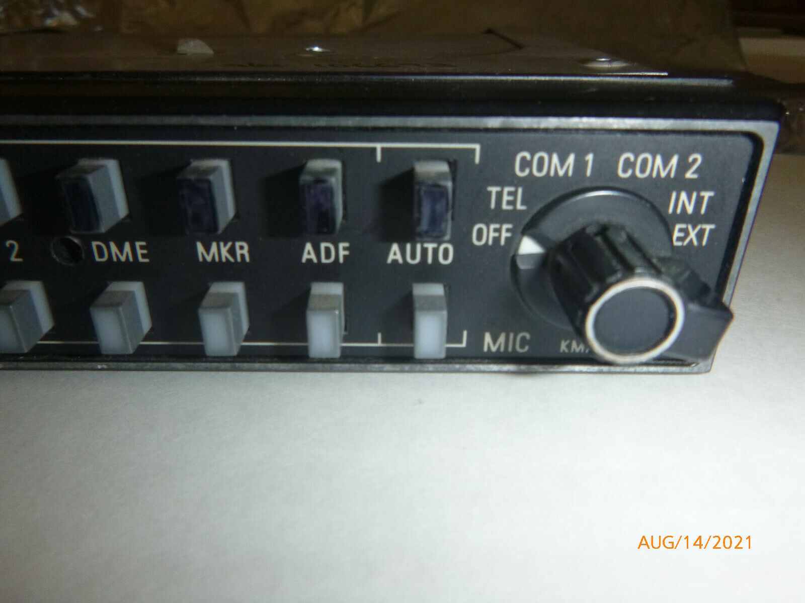
AUTO – this is probably the most confusing button for pilots when they first work with the audio panel. The rotary switch on the right side of the KMA 24 can be set for either COM 1 or COM 2. The rotary switch controls the transmission frequency. So if you have COM 1 selected with the rotary switch, when you push the transmit button, you are transmitting on COM 1. The AUTO button allows you to automatically slave the received audio information to whichever frequency you have selected with the rotary switch. By pressing the AUTO button in the bottom row (headset), you will automatically hear the transmissions from either COM 1 or COM 2, depending on which one has been selected by the rotary switch. So with AUTO selected, you may switch back and forth between COM 1 and COM 2 with the rotary switch without having to reselect COM 1 or COM 2 using the push buttons. If you desire to hear audio from the other com radio, you may do so by simply pressing the appropriate button for either speaker or headset. For example you are listening and transmitting on COM 1 but would like to listen to ATIS at the same time. You may do this by putting the ATIS frequency in COM 2 and pressing the COM 2 button for either speaker or headset. Warning – it can be confusing to try to listen to two frequencies at the same time.
12.
The rotary switch on the right side is used to select the desired transmitter for the cockpit microphones. COM 1 and COM 2 have been previously discussed. The INT position selects cabin intercom. This allows the crew to address the passengers over the cabin speaker. The EXT position allows the crew to address people on the ramp through an external ramp hailer speaker, if one is installed.

